eheal6520
Member
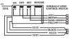
Hey Gang, over the weekend I added some farkles, one of them is the Rostra cruise control. Well it's not working. I followed the installation instructions from http://users.tpg.com.au/roger38//Rostra%20XT1200Z.htm, all went well. When I went to do the diagnostics, I could not get the led light next to the dip switch to come on. Neither will the cruise turn on normally. I have installed the audiovox vacuum version on my C90, so I am familiar with the setup. I have done all the continuity checks from the pad to the servo, also all good. The installation manual says there is a power problem, check the Red and Brown wires. With power on, I have 12vdc at the brown wire on the servo connector and 12vdc at the red wire on the control pad side of the control pad connector.
I did a voltage check of the control pad buttons and got the following:
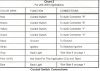
resume button, Yellow wire at the servo - unpushed 0vdc, pushed 12vdc
set button, Dark Green wire at the servo - unpushed 0vdc, pushed 12vdc
off button, Brown (Red/Brown at the servo) - unpushed 0vdc, pushed 0vdc
on button, can't test, no return path except thru the other buttons.
Questions:
1. Is there a return path for the cold side of the On Button?
2. Is there suppose to be 12vdc on the Red/Brown wire when the Off Button is pushed?
Right now it looks like I have a bad control pad. No return for the On Button and No 12vdc for the Off Button.
BTW, I did a continuity check of the buttons. Resume and Set appear to be working ok, but On and Off do not. Resume and Set short when I press the buttons, On and Off remain open when I press the buttons. Baring some internal circuity on the pad.
What I would like is for someone with a working system to check the continuity of the On and Off buttons. Also check if 12vdc is present on the Red/Brown wire at the servo when the Off Button is pushed.
Thanks, Ernie
I did a voltage check of the control pad buttons and got the following:
resume button, Yellow wire at the servo - unpushed 0vdc, pushed 12vdc
set button, Dark Green wire at the servo - unpushed 0vdc, pushed 12vdc
off button, Brown (Red/Brown at the servo) - unpushed 0vdc, pushed 0vdc
on button, can't test, no return path except thru the other buttons.
Questions:
1. Is there a return path for the cold side of the On Button?
2. Is there suppose to be 12vdc on the Red/Brown wire when the Off Button is pushed?
Right now it looks like I have a bad control pad. No return for the On Button and No 12vdc for the Off Button.
BTW, I did a continuity check of the buttons. Resume and Set appear to be working ok, but On and Off do not. Resume and Set short when I press the buttons, On and Off remain open when I press the buttons. Baring some internal circuity on the pad.
What I would like is for someone with a working system to check the continuity of the On and Off buttons. Also check if 12vdc is present on the Red/Brown wire at the servo when the Off Button is pushed.
Thanks, Ernie