Final-Drive Leaking, Seal Replacement

SkunkWorks

Well-Known Member
Joined
Sep 13, 2018
Messages
1,783
Location
Colorado
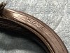
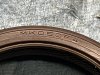
At the end of last season, during my last ride in the fall, I had noticed a bit of gear-oil had dripped onto the rear wheel.
You could see the telltale streaking on the tire from it spinning.
I had simply parked the bike in the Garage. I already had the output-seal on the shelf, so I figured I would get to it at some point.........

Fast-forward to this weekend.
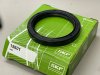
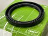
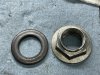
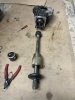
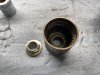
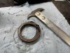
I pulled the rear wheel to inspect and replace the output seal.

IMG_7166.JPG

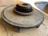
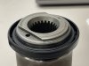
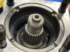
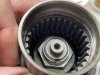
Cush-Drive Plate is dry....................Hmmmm, figured it would have some gear oil wetness on it.

IMG_7165.JPG

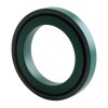
Does not appear that it was leaking from the output seal.
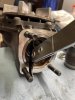
So I take a look underneath.

IMG_7164.JPG

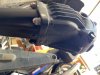
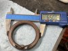
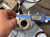
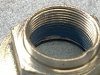
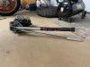
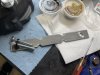
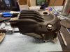
Seems like it was leaking out of the drain hole, and blowing back all over the swingarm and final-drive housing.

IMG_7167.JPG

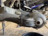
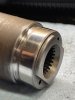
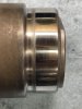
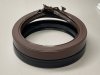
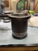
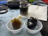
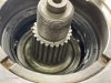
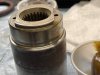
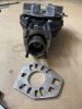
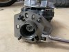
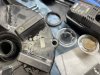
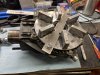
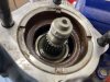
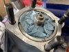
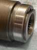
So I drained the fluid out, and removed the final-drive assembly from the swingarm.
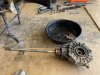
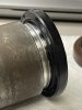
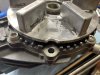
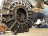
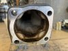
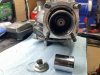
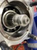
IMG_7169.JPG

Sure enough!
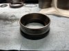
Gear oil inside the Swingarm leaking from the input seal.......

IMG_7168.JPG
 

SkunkWorks

Well-Known Member
Joined
Sep 13, 2018
Messages
1,783
Location
Colorado
I already have the output seal, but looked up the Yamaha part-number for the input-seal.
Called around to the Yamaha shops in town...........Of course nobody has one (I sorta expected that)
Ordered one from Partzilla, and I should have it by next weekend.

Removing the driveshaft from the final-drive assembly, it did not just separate easily.
The dust-seal was holding it in there pretty good, so I used a plate from a ball-joint press tool and my fork-seal driver as a slide-hammer to pull it out.
No problem!

IMG_7172.JPG

Then I took the whole assembly down to the laundry tub, sprayed it with some degreaser/water mixture, and brushed the whole thing clean.
Did the same with the Cush-drive adapter.
Rinsed and dried, I brought it back to the workbench.

IMG_7175.JPG

I do not have the special Yamaha drive-coupler holder tool to remove the coupler-nut.
I figured I could just use the cush-drive plate, and lock the output to the housing to keep it from spinning.
I fabricated a holder-bracket, and went down to ACE-Hardware and got two 8 x 1.25 x 50mm bolts.
Removed two opposite gear retainer-plate screws, and bolted the cush-drive to the housing.

IMG_7174.JPG

Using my air-impact and a 27mm socket, the coupler-nut came off without much fuss.

IMG_7176.JPG

The Drive-Coupler then just slides right off the shaft, exposing the input-seal.
There is also a flat washer down inside there.
IMG_7177.JPG

Sure-enough...............Input seal was leaking.

IMG_7178.JPG
 

SkunkWorks

Well-Known Member
Joined
Sep 13, 2018
Messages
1,783
Location
Colorado
I used my seal-puller. It was stuck in there, but I got it out without too much trouble.

IMG_7179.JPG

IMG_7180.JPG

I used a shop-towel dampened with some gear oil to clean all the dirt and gunk out of the housing where the seal fits in.
I was careful not to push anything into the bearing.

IMG_7181.JPG

Then I stuffed a couple clean shop-towels down in there to prevent anything from getting in there while I wait for the new seal.

IMG_7182.JPG

Inspected the Drive-Coupler.
There is just a little bit of a groove on it where the seal has been riding..........You can barely feel it with your fingernail.

IMG_7184.JPG

It has exactly 46,450 miles on it.
I will try to polish it using some strips of emery-cloth.
I have a couple different grits up to 320, and then some wet/dry paper up to 800.
I'll work on that this week while I'm waiting for the seal to come in.
 
Last edited:

Jlq1969

Well-Known Member
Joined
May 5, 2018
Messages
1,805
Location
Argentina
The trench is minimal...if you have doubts that the new seal can seal correctly in that trench, wearing out the working area of the seal would leave you with the same doubt. I personally would either change the brand of the seal (in case the seal lip was located in another place, or I would look for a double lip seal, or two thinner seals, that give the thickness of the original seal, to change the place where the new lip seal works., another option is to get a retainer with one smaller inner measurement, but do not use this smaller retainer (it will deepen the trench more)...I would use the spring from this small retainer, in the original retainer..If the leak started because of the trench, a new seal should work better in that trench, but perhaps for fewer miles than the original one did.
It really seems like it's minimal...I don't know if it's worth wearing out the entire piece...Maybe I would just replace the seal with a new one, and leave what I said or the wear of the piece, for the next change...I would also check the radial movement of the Bearing
 
Last edited:

holligl

Find the road less traveled...
Joined
Nov 13, 2015
Messages
2,255
Location
IL/AZ
Brilliant way to lock the hub! I had suggested strapping the whole wheel to the hub, but your way is cleaner. Good to hear you can remove the seal without removing the retainer nut. Mine was a bear to get out, with the retainer nut removed.
Just a note, the washer for the coupler nut is supposed to be Uni-directional. Pay attention to which way it goes.
As these bikes get more miles, it looks like this is becoming a more common repair.
 

SkunkWorks

Well-Known Member
Joined
Sep 13, 2018
Messages
1,783
Location
Colorado
The groove is not really bad at all.
I've replaced a lot of seals over the years, and I've seen far worse.
I'm not concerned about finding other suitable seals that may or may not work, or trying to fit a repair-sleeve on it.
I'm putting a Yamaha seal back in there, and I'll polish the groove out with some emery cloth.
I'm not going to spend a lot of time on it though, cause there's barely a groove there............
I'll put it back together and run it. I'm not that concerned about it.

There is no runout in the shaft bearing. It is solid, with no play that I can feel.
 
Last edited:

SkunkWorks

Well-Known Member
Joined
Sep 13, 2018
Messages
1,783
Location
Colorado
Brilliant way to lock the hub! I had suggested strapping the whole wheel to the hub, but your way is cleaner. Good to hear you can remove the seal without removing the retainer nut. Mine was a bear to get out, with the retainer nut removed.
Just a note, the washer for the coupler nut is supposed to be Uni-directional. Pay attention to which way it goes.
As these bikes get more miles, it looks like this is becoming a more common repair.
I did see that the washer appears to be different on one side. I kept it in the correct orientation when I pulled it out of the coupler.

I would say to anyone that may have a bike that is getting up there in miles, to keep a set of these seals on the shelf cause you will have to replace them at some point.
Nobody seems to stock them at the Dealerships either, so you will have to wait for one to be shipped.
 

SkunkWorks

Well-Known Member
Joined
Sep 13, 2018
Messages
1,783
Location
Colorado
can i ask, is that holder bracket a peices of ally roughly 5mm thick

rob
It's a piece of Steel flat-stock that I had in the garage from another project.
It's 1/8" thick and either 1" or 1.5" wide............I can measure it when I get home.

is that imput seal, part number looking on the webb 93102-50009

rob
Yes. That's the seal part number that I ordered: 93102-50009-00
 

SkunkWorks

Well-Known Member
Joined
Sep 13, 2018
Messages
1,783
Location
Colorado
YES, part number 15

The section of that part where the Seal rides on is a "raised" area above the circumference of the Coupler just ahead of it.
If you look closely at my picture I posted, you can see it is slightly smaller diameter just in front of the seal interface surface.
The drawing that Yamaha shows looks correct, in that the smaller diameter section just looks like a groove in their drawing.
The shiny-groove in my picture on the seal interface is actually worn into the Coupler by the seal itself.
This is not uncommon, as any dust that gets in there acts as a slight abrasive.................Mine is not actually that bad, and you can barely feel it with your fingernail.
I have seen engine crankshafts and Axles with grooves worn so deep by the seals that the crankshaft or axle-shaft is unusable............They make "Repair Sleeves" for the common ones. Another fix would be to weld up the groove, and have it re-machined to the correct size. OR, you could do what one member did and actually machine the diameter smaller so that you can press-fit a new seal interface that is made of a harder material.
They also make "Repair Seals" that are offset and move the lip of the seal to a new part of the interface, so it is not riding in the worn groove.
I doubt very highly that you could find one for this application though.
 

RCinNC

Well-Known Member
Joined
Aug 30, 2014
Messages
2,876
Location
North Carolina
Thanks Skunkworkd. I deleted that post; I kept looking at the drawing and figured that I must have been wrong about the groove.
 

Jlq1969

Well-Known Member
Joined
May 5, 2018
Messages
1,805
Location
Argentina
They also make "Repair Seals" that are offset and move the lip of the seal to a new part of the interface, so it is not riding in the worn groove.
I doubt very highly that you could find one for this application though.
This is a repair seal when the trench is very deep. The seal rotates on a sealed cup. It is usually a better solution than filling a trench... but as Skunk says, it does not always come in the necessary measurements.
IMG_9510.jpegIMG_9509.jpegIMG_9508.jpeg
 

SkunkWorks

Well-Known Member
Joined
Sep 13, 2018
Messages
1,783
Location
Colorado
can i ask, is that holder bracket a peices of ally roughly 5mm thick

rob
The steel flat-bar that I used is exactly 1" wide by 1/8" thick...
I had to grind the relief notches to fit in between the drive-lugs.

You will also have to grind very tiny notches in the outside of the cush-drive plate to allow the bolts to reach the existing holes in the gear-housing.
I'll show a picture of those once I have it back together and disassemble my holder-bracket.
 

SkunkWorks

Well-Known Member
Joined
Sep 13, 2018
Messages
1,783
Location
Colorado
Spent a total of about 20 minutes on the seal surface of the Drive Coupler, using strips of emery-cloth.
Started with 160, then went to 320 grit.
Next I switched to strips of wet/dry sandpaper.
400, then 600, then 1000 grit.

Did not take much polishing at all, and it's hard to tell where the groove was!

IMG_7211.JPG

IMG_7212.JPG
 

SkunkWorks

Well-Known Member
Joined
Sep 13, 2018
Messages
1,783
Location
Colorado
I was set on putting this bike back together this weekend. The weather is supposed to be nice, and I want to ride!
Got an alert on Thursday that my shipment of the Input-Seal was delayed, and would not arrive until early next week...............Bummer!

Having a really slow day at work yesterday, I had plenty of time to do a bunch of research.
I used my measurements as well as the listed specs in the Koyo Charts. (the OEM seal was manufactured by Koyo)

IMG_7213.JPG

IMG_7214.JPG

IMG_7215.JPG

IMG_7216.JPG

I scoured the other Brands Seal-Catalogues, and came up with a near-perfect match!

IMG_E7226.JPG

IMG_7217.JPG

IMG_7218.JPG

And sure enough....................The local NAPA store that I deal with had them in stock!

IMG_7227.JPG

It was $11.42 with Tax.

IMG_7219.JPG
 

Attachments

SkunkWorks

Well-Known Member
Joined
Sep 13, 2018
Messages
1,783
Location
Colorado
It's a Nitrile-Rubber Seal, and their listing shows the common application as an Automatic Transmission/Transaxle Front-Pump seal.

It fits in all the right ways..............has a rubber-coated outer shell and a dust-lip, just like the OEM one.
The shell is exactly 1mm shorter than the OEM one (8mm vs 9mm), but that shouldn't matter as it's a tight press-fit into its outer bore.
IMG_7221.JPG

IMG_7222.JPG

IMG_7223.JPG

Once I got home from work, I thoroughly washed and dried the Drive Coupler to remove any traces abrasive dust from my emery-cloth/sandpaper polishing.

I used an old bearing-race that was close in size, and a stack of adapters to tap the new Seal in place.

IMG_7228.JPG

IMG_7230.JPG

Fully seated!

IMG_7231.JPG

I set aside some Lithium-based wheel-bearing grease, and a spoonful of Moly-grease in a couple of condiment-containers for use during assembly.

IMG_7232.JPG

I wiped a thin film of the wheel-bearing grease on the lip of the Seal, and on the sealing-surface of the Drive Coupler, and then inserted it onto the splined shaft.

IMG_7236.JPG

IMG_7235.JPG

Next is the Washer that goes in before you thread the nut on.
It is supposed to only go on one way.
You cannot really mess it up because it has the word "OUT" stamped right onto it.

IMG_7237.JPG
 

SkunkWorks

Well-Known Member
Joined
Sep 13, 2018
Messages
1,783
Location
Colorado
Yamaha shows in the assembly procedure to replace this Nut with a new one............I didn't realize this a week ago when I ordered the Seal, so I didn't order one.
I'm going to re-use the original one. It's torqued down pretty tightly, and staked in place, so it shouldn't be an issue.

Yamaha does show to use "Threadlock" on the threads during reassembly.
I'm using medium-strength Blue.

IMG_7239.JPG

Yamaha torque-spec shows to tighten it to 108 ft/lbs

IMG_7240.JPG

Since I heave the Output locked to the Housing, I was not concerned with the gears turning during tightening.
I thought about how to keep the Housing from twisting during the torque process, and then remembered I have a Differential-Yoke Tool for setting Pinion-Bearing preload.

IMG_7244.JPG

I needed to clearance the center-hole slightly with my Dremel to fit over the Drive-Coupler, and also enlarge two of the Slots to fit over the mounting Studs.
It fit over them perfectly!

IMG_7243.JPG

The 108 ft/lb reading was super easy to achieve with this setup!

IMG_7241.JPG

The last thing to do on the Input side was to "Stake" the Nut in place, so that it can't back itself off.
I used a center-punch. It's pretty deep inside there, so you can't really get the optimum angle.
I'll order a new Nut to keep on the shelf in case I need to do this job again in the future.

IMG_7264.JPG

Removed my Home-made Output-Lock Tool, and labeled it.

IMG_7262.JPG

I Zip-tied the longer housing-bolts to it, so I don't loose them.

IMG_7263.JPG

This shows the small Notches that have to be cut into the edge of the Cush-Drive Plate in order to use this method to hold the final-drive gears from turning.

IMG_7245.JPG

IMG_7246.JPG
 
Top