Fan not kicking on at 221f + as it should

rtwpaul

Member
Joined
Sep 20, 2014
Messages
77
Location
United States
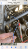
These are the details
  • 2012, with 103000 miles
  • the bike has never been dropped on the left side, so not bent
  • tested I have power at the connector and it jumps to 13.77 volts when the bike is over 221f like it should
  • to date replaced the fan, even though it wasn't bad
  • replaced the relay
  • no fuses have EVER blown
  • replaced the thermosensor
  • replaced the thermostat
  • replaced the coolant
  • no obvious wire fraying
  • no other electrical issues at all
  • no error codes
  • have disconnected the battery to see if there is some kind of reset to the ECM, made no difference
with a new fan and old fan, I tested it on an independent car battery at 12.8 volts it spins as it should
I then tested it on the bike battery (not running) at 13.4 volts it spins as it should
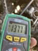
I tested the connector under the air box, it shows about 0-2 volts when the bike is cool, then ran the bike to over 221f and the connector shows 13.77 volts, attached the fan, and NOTHING, but the voltmeter jumps to 60 volts, no fuse blows, and the fan is still good when tested on the other batteries
IMG_0943.jpgIMG_0952.jpg

to triple check, I immediately connected the fan directly to the bike's battery and its still good so didn't burn up, same on the car battery

At this point totally confused why at three different sources with over 12.8 volts it works in two places and not where it should, but makes the voltage increase...its two wires +/-

Open to any ideas about what obvious thing I'm missing, or what the issue might be???
 
Last edited:

Highwayman

Well-Known Member
Joined
Jun 25, 2019
Messages
405
Location
Southern California
Are you checking voltage between both terminals at the connector? Or just power side? Sounds like an issue with ground side. It doesnt say specifically and alot of guys just clip the meter neg lead to an engine ground wherever and not check both sides of connector (which will show power to connector, but nothing for ground side).
 

rtwpaul

Member
Joined
Sep 20, 2014
Messages
77
Location
United States
Are you checking the voltage between both terminals at the connector? Or just power side? Sounds like an issue with ground side.
I've tested power at the + and using the bike as ground, tested it with the connector connected at the end of two wires (I have spare connector) and touching the connector pins where they are plugged in all three get the same result

IMG_0953.PNG
 

rtwpaul

Member
Joined
Sep 20, 2014
Messages
77
Location
United States
Are you checking voltage between both terminals at the connector? Or just power side? Sounds like an issue with ground side. It doesnt say specifically and alot of guys just clip the meter neg lead to an engine ground wherever and not check both sides of connector (which will show power to connector, but nothing for ground side).
I just took a secondary ground wire and attached it to the ground from the connector and took that to ground, still no fan, if I detach the ground wire from the fan switch and go directly to ground eliminating the ground wire in the system and creating my own independent ground, still no fan
 

Sierra1

Well-Known Member
Joined
Nov 7, 2016
Messages
15,024
Location
Joshua TX
Are we sure that the thermal sensor (thermometer) is good. . . . even though it's new?
 

rtwpaul

Member
Joined
Sep 20, 2014
Messages
77
Location
United States
Are we sure that the thermal sensor (thermometer) is good. . . . even though it's new?
I would say yes because below 200f I get around 4 volts with the bike running, once it hits 221f+ voltage jumps instantly to around 14 volts, regardless if I use the connector ground or an independent ground or a combined ground

The same happened with the old thermosensor too
 

Highwayman

Well-Known Member
Joined
Jun 25, 2019
Messages
405
Location
Southern California
Hmmmmm.... Have you tried hooking the fan to that secondary connector via those leads?

From what youve said so far it sounds like maybe the connector or fan. If you have 12v and ground on those test leads, the bike is giving what the fan needs. I know you bench tested the fan, but if you have 12v and ground at the ecm harness, the bike is commanding it on. It would need to be fsn connector, wiring or fan. If you have 12v and ground at the tester leads, the next Id do is reconnect the fan and backprobe the connector on the fan side or pierce the wiring with a couple needles and see what you have right at the fan. I know its hard to diagnose on the net. Just going off what Ive read and my thoughts.
 

StefanOnHisS10

Converting fuel into heat, noise and a bit motion
Staff member
Global Moderator
Joined
Apr 8, 2020
Messages
2,181
Location
The Netherlands, Friesland.
Hi Paul! On a customers bike I repaired, who had no brake lights through the front lever, I measured 12V throughout the system. Finally I found that one wire was scraping the frame and was almost cut. From all the little copper wires in that one lead only one was still connected. That was enough to let 12V pass but not enough to let the amp’s pass. Fixed the wire and everything worked. Trying to say here that the measuring can put you on the wrong path.
Just my thoughts.
Stefan
 

Squibb

Well-Known Member
Joined
Aug 10, 2014
Messages
1,067
Location
Bedford, UK
Given the test & replacement part regime here, I'm wondering nevertheless whether this is the fan relay playing tricks. Simple enough to remove & use a temporary jumper lead.

The fan should switch on at 221F, 105C so there should be no significant variation there. However, we need to remember, the temp sensor doesn't turn the fan on; the sensor feeds a variable voltage to the ECU, temperature dependent, and when that voltage equates to 221/105 the ECU then sends a switching current to the fan relay, which then turns on the fan.
 

SparrowHawkxx

Active Member
Joined
Dec 9, 2012
Messages
203
Location
Oklahoma
Agree with Highwayman, something like this is hard to diagnose on a message board. From what you've said it sounds like, other than the fan connector and the ecu, you have eliminated the main components as being the problem; new fan, new relay, new coolant temperature sensor.
Don't know that I can help any, other than throw some thoughts out there to get you thinking about this differently.
  • The only obvious thing I see is the meter reading on the auto scaling meter switched to millivolts (mV) so it didn't jump to 60 V, it dropped to 0.06 V. If it was 60 V I would be really concerned.:eek:
  • Seems like the fan connector would be the next thing to eliminate. I'm not familiar with that connector, can you get a tool in the back side to release the pins from the connectors? At least inspect the pins inside of the connectors, but if you can get the pins out you could jumper the blue wire pins between the two connectors and same for the black wires. This would ensure there is a good connection and no leakage between the blue and black connections.
  • Or, another option is to use Posi-Tap connectors to jumper the blue wires together and the black wires together. Just leave the connectors separated for this test.
  • Was the recall recently done for the sensors wiring harness? This corrects the problem with the APS/TPS splices to the ECU wires. This recall involves removing pins from one of the ECU connectors and replacing them with pins from the wires in the new sub harness. Just a thought maybe the pin to the fan motor relay was disturbed during the process. Not likely, but possible.
  • Yes, the coolant temperature sensor does not go directly to the fan rely, it goes to the ECU and the ECU determines when to send the signal to the relay. The temperature at which the fan kicks on can be changed in the ECU.
 

MattR

Well-Known Member
Joined
Nov 16, 2019
Messages
1,176
Location
North Hampshire UK
Where are you getting your temp readings from? Is it from the bikes dash? If so have you tested it to make sure it is reading true?


Sent from my iPhone using Tapatalk
 

scott123007

Well-Known Member
Joined
Jul 27, 2012
Messages
1,484
Location
Jupiter, Florida
I like what Stefan is suggesting. I would attach a wire to the positive wire that goes to the fan and attach it to one side of a 20 amp fuse. I would then attach another wire to the other side of the fuse. Start the bike up and run it until it spikes the voltage to run the fan. Then touch the positive wire coming from the other side of the fuse, to ground. If the fuse does not blow, it will probably melt the remaining wire strand or two that's making that circuit show voltage, and now it will show no voltage. You'll just have to find where the break is after that.

If the fuse blows, then I don't know what the hell is going on with it. LOL
 

Jlq1969

Well-Known Member
Joined
May 5, 2018
Messages
1,805
Location
Argentina
What would I do if it were my motorcycle?….1) I unplug the fan and connect it directly to a battery to cool down when necessary
2) I start the engine and hope it warms up…(if the dashboard shows that the temperature rises , as it normally does, it is a sign that the temperature sensor is in perfect condition
3) When it reaches 105c I connect the fan (externally) to cool the engine and with a tester, first I test the signal on the disconnected plug of the fan, if - and + signal arrives, but above all I check that the - on the plug has continuity with the chassis (full -). Relay is controlled by an ecu, the signal that the ecu sends to activate the relay is the (-)….so more than checking the +, it would check that the signal from the ecu reaches the relay (the -)….In some connections electrical controlled by an ecu, you can have: a) signal + permanent in the accessory and the only thing missing is the - sent by the ecu, or b) a accesory permanent to the chassis (-) and the ecu sends the + through a relay... but that relay (controlled by the ecu), is normally activated with a signal (-) that is sent by the ecu…when that signal (-) that the ecu sends fails….the problem is internal to the ecu, but it could also be that the ecu is not receiving any (-)..” sometimes”, ecus have “several (-) inputs, precisely because they control several functions at once
Edit:
Normally, the ECUs have inputs (+) of consumption, but they also have inputs (+) of "control"... that is, an ecu that controls a relay, it sends a signal (-) so that the relay turns on. In the relay you have on one side the coil that activates it (+ permanent and - sent by the ecu) and on the other side the + circuit to be joined. When the + circuit joins, on the one hand it sends current to the accessory and on the other hand it sends current to the ecu to “inform” it that the circuit joined….if this + did not reach the ecu, it would know that the circuit “ did not join” due to failure in the relay and shows an error code. this positive that "enters" the ecu, is not for consumption, this is a + check
 
Last edited:

rtwpaul

Member
Joined
Sep 20, 2014
Messages
77
Location
United States
Thank for all the responses,

the one issue with trying to find this problem is you need the bike above 221f, so it is a lot of thinking you found it, connecting everything back up, and running it to 221f+, to find out it wasn't that then working around a very hot motor to try the next thing, or letting it cool...kind of annoying and very time consuming

I will get on it tomorrow and systematically check and itemize everything, I did lead myself in the wrong direction thinking (wrongly) 60V, when it was 60mV, bad eyes in bright light!!!

My thought about it at this point is I have a partially broken ground that will show 12V+ on a meter but then add resistance (fan) and there isn't enough ground to make it run, which of course is better than too much voltage, or is the opposite and the power (blue) is partially broken...either way its like chasing a ghost

One question to the collective, ground wires, there must be multiples/spider legs, and guessing they must be grounded in different areas otherwise I would have multiple issues, I'm finding the coupler in the FSM but not a connection point to the frame, because they don't show the rear tray wiring layout in the FSM...anyone happens to have a photo of that?

#12 is the negative wiring coupler, so guessing it grounds somewhere near the ECM to the frame
Screen Shot 2022-04-04 at 3.27.47 PM.png?
 

Jlq1969

Well-Known Member
Joined
May 5, 2018
Messages
1,805
Location
Argentina
I sent you a pic of the electrical circuit, even knowing that the resolution is of poor quality (practically unreadable). The file is in pdf and it is not possible to upload it. It's taken from the ss manual of the S10


AC0DF0E6-BD3A-4072-9B91-D36B814CF2A8.jpegF464ED34-EDBD-4762-BC1B-E7E39CC0F2AD.jpeg
 

SparrowHawkxx

Active Member
Joined
Dec 9, 2012
Messages
203
Location
Oklahoma
Thank for all the responses,

the one issue with trying to find this problem is you need the bike above 221f, so it is a lot of thinking you found it, connecting everything back up, and running it to 221f+, to find out it wasn't that then working around a very hot motor to try the next thing, or letting it cool...kind of annoying and very time consuming

I will get on it tomorrow and systematically check and itemize everything, I did lead myself in the wrong direction thinking (wrongly) 60V, when it was 60mV, bad eyes in bright light!!!

My thought about it at this point is I have a partially broken ground that will show 12V+ on a meter but then add resistance (fan) and there isn't enough ground to make it run, which of course is better than too much voltage, or is the opposite and the power (blue) is partially broken...either way its like chasing a ghost

One question to the collective, ground wires, there must be multiples/spider legs, and guessing they must be grounded in different areas otherwise I would have multiple issues, I'm finding the coupler in the FSM but not a connection point to the frame, because they don't show the rear tray wiring layout in the FSM...anyone happens to have a photo of that?

#12 is the negative wiring coupler, so guessing it grounds somewhere near the ECM to the frame
View attachment 90425?
That white connector right behind the battery is open at the top and gets sand in it, causing a resistive connection. The black/white wire coming out the bottom of the connecter goes to a ground on the engine, below the CCT and towards the center a couple inches (easy to trace the wire).
I cleaned mine out and sealed the top off.

I haven't heard of this causing a fan problem but it has caused some problems for others. Its easy enough to take care of and whether it fixes your problem or not, its something else to eliminate.
 
Last edited:

Highwayman

Well-Known Member
Joined
Jun 25, 2019
Messages
405
Location
Southern California
I do have a question as far as the voltage drop speculation. Have you tried 1st checking voltage at fan connector at 221 disconnected from fan and then with T pins or equivalent pierced through wiring at fan reconnect the connector and check at pins? If you have a voltage drop (IE open or compromised circuit) itll show up at the pins with the connector attached and load of fan in circuit.

At this point Id be ohming out the wires at this point between sections. IE ECM to relay connectors. Relay to fan connectors. Etc. That will show you very quickly if you have any open in the wiring.
 
Last edited:

rtwpaul

Member
Joined
Sep 20, 2014
Messages
77
Location
United States
getting into it right now, taking a slightly different approach so I can document to try and make sense of for me and for you, and put the multi meter on the right setting!!!

cold bike, battery 13.6 V
at connector 0V
at fuse 0 V

Bike running 14.1 V
at connector 0 V
at fuse 13.7V

testing the fuse, bike below 221f
using - at connector + at battery 13,7 V
using +at connector - at battery 0 V

To me, all the above is correct and as it should be

using multimeter attach to pins of connector +/- and bike running
below 200f 0 V
at 217f power at connector 13.2 V

turn off running bike to cool, but leave ignition turned on
at 217f+ 13.2 V
at 205f 0 V, and I hear an audible click from the relay as it went to zero/ turn off connection

doing the same as above but with a fan connected
the bike ran to 217f which is when mine seems to power on, nothing, got all the way to 235f, and no fan and no power at the connector
Tried the above with a secondary independent ground attached directly to the neg at the battery, got the same result, nothing, tried it again with an independent frame ground, still nothing...so it is definitely not a ground issue its a power issue

The result and next direction is to cut open the $800 wire harness and trace back the + side (blue) to look for broken sections as @StefanOnHisS10 has suggested...wish me luck!!!
 
Last edited:

hulkss

Active Member
Joined
Feb 22, 2022
Messages
165
Location
Wisconsin
I had a BMW where a connector pin had backed out of a connector shell. An assembly tool at the factory was damaged and was not fully seating one of the pins. Happened to a lot of bikes.

Pull apart all relevant connectors and look inside if you have not already done that.
 

SkunkWorks

Well-Known Member
Joined
Sep 13, 2018
Messages
1,783
Location
Colorado
I'm going to make one other suggestion to check.
Maybe you've already tried this?
Run jumper wires from the female fan-connector to the male fan-connector and try your temp rest again.
I work with a lot of equipment, with a lot of fiddly electrical connections.
Sometimes when there is a male-to female pin interaction within a connector, the female side gets "enlarged" due to vibration or sometimes by wiggling the connection while plugging/unplugging it.
(or sometimes jabbing a test-lead into it)
The pins sometimes fail to make the connection after this happens, or make such a loose "barely touching" connection that it won't pass the proper amps.

Before you dig through the harness, maybe check that this hasn't happened with your fan-connector.
 
Last edited:
Top