Electrical modifications are a challenge for a lot of owners. So I thought I would post what I came up with just to help provide ideas for others thinking about how to wire up that latest farkle, or several! ::26::
When I picked up my new S10 in August I had been thinking about all the mods and upgrades I wanted to make for some time. I realized that many of them need electrical power and switches to control them. The list so far is: LED flood lights, cruise control, grip heaters, seat heaters, and a Super Sport mode (i.e. clutch switch short via relay). I also want to have a full time Digital Volt Meter (DVM) so I can monitor the health of the charging system at all times as I switch in different loads so as not to create an overload that goes unnoticed until the next time I try to start the beast up. With my luck, it will be when I am 1,000 from home. : So that is 5 switches and a meter. And that is in addition to the other non-stock handle bar area controls like a cruise control panel, remote button to scroll the display, seat heat thermostat, and GPS. Clearly I would have to add some kind of panel to hold some of this stuff or I would quickly run out of room. In addition I wanted to power all additions with a separate fuse block. This fuse block is fed by a relay that turns on only when the ECU determines that the engine is running. The ECU has a control line for that and it activates the head light relay. I just tied into the output of the head light relay.
I had several goals here. One is to make sure I completely isolated my stuff from the bike’s electrical system so nothing I do can cause the magic smoke to leak out. I am an electrical engineer but still manage to screw up and leak smoke with alarming regularity. :-[ I also want to have each device on a separate fuse.
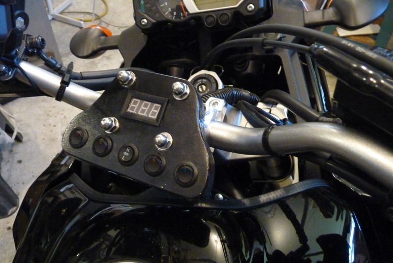
So here is what I ended up with. The switches are toggle and light up LED’s when turned on.
Here it is mounted on the bike:
And here is the wiring underneath. This explains better than words how it is constructed.
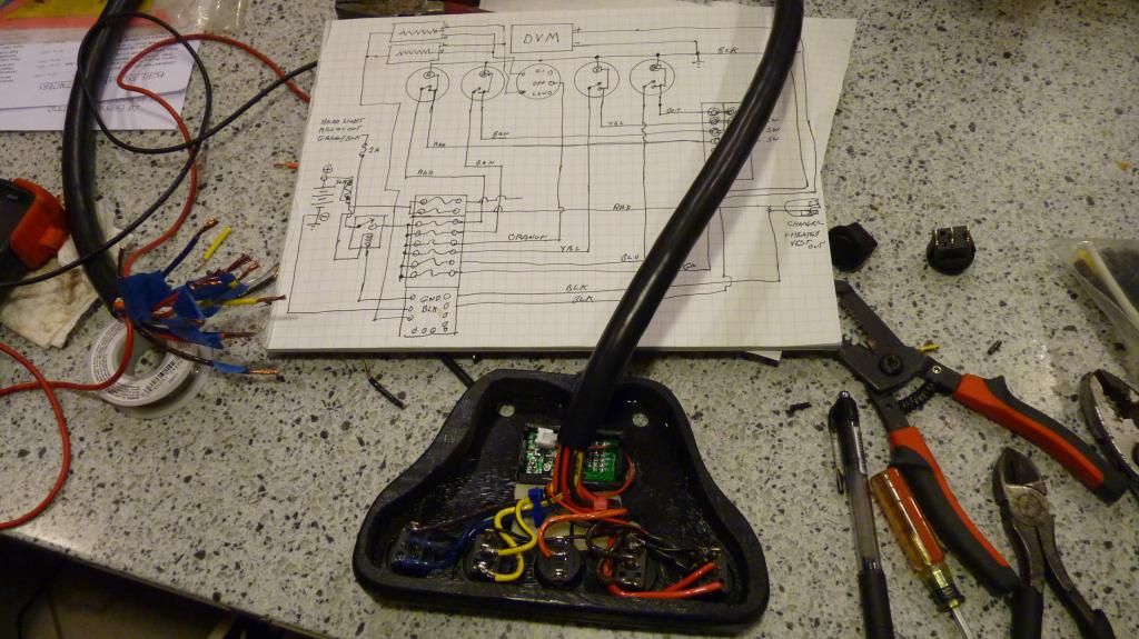
And this one is the finished panel under test prior to install.

The panel itself is made from 3/16” aluminum plate. It is held to the handle bars by two U bolts, 4 cap screws, and a couple of spacers underneath. I added a skirt of 3/4" plywood around the bottom outer edge just to give it some thickness and help protect the electrical parts. I just cut it out on the band saw and then cut out most of the middle to leave a thin strip. I found a 12 conductor cable at the local electrical surplus store. I used the cable to connect the panel to the fuse block down in the battery bay for switch power and to a terminal strip for switched power from the switch. Then all I had to do to add something was pick up the switched power at the terminal strip.
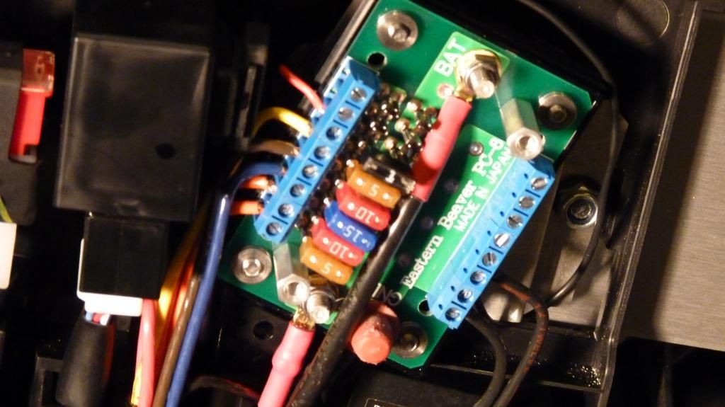
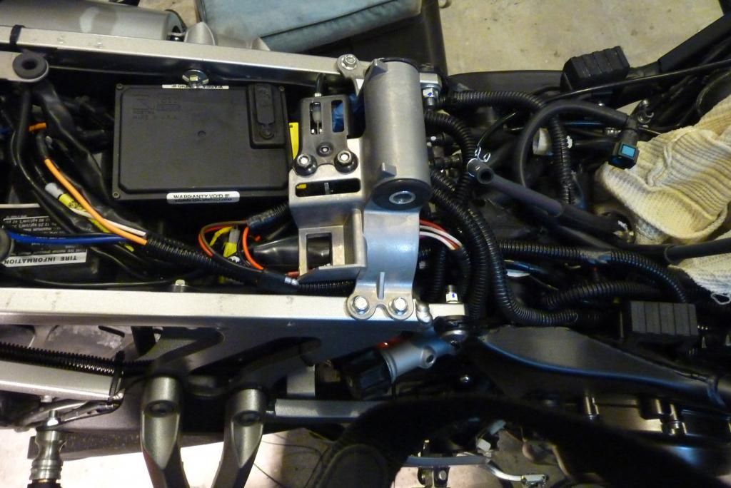
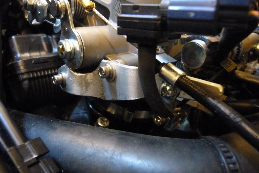
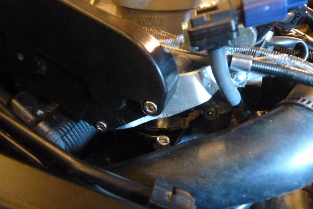
For the fuse block I used the very nice unit from Eastern Beaver. It came in a kit with the control relay. The first thing to figure out was where to mount it. A made a mounting plate from thin aluminum and bolted it to the back side of the rectifier as shown here:
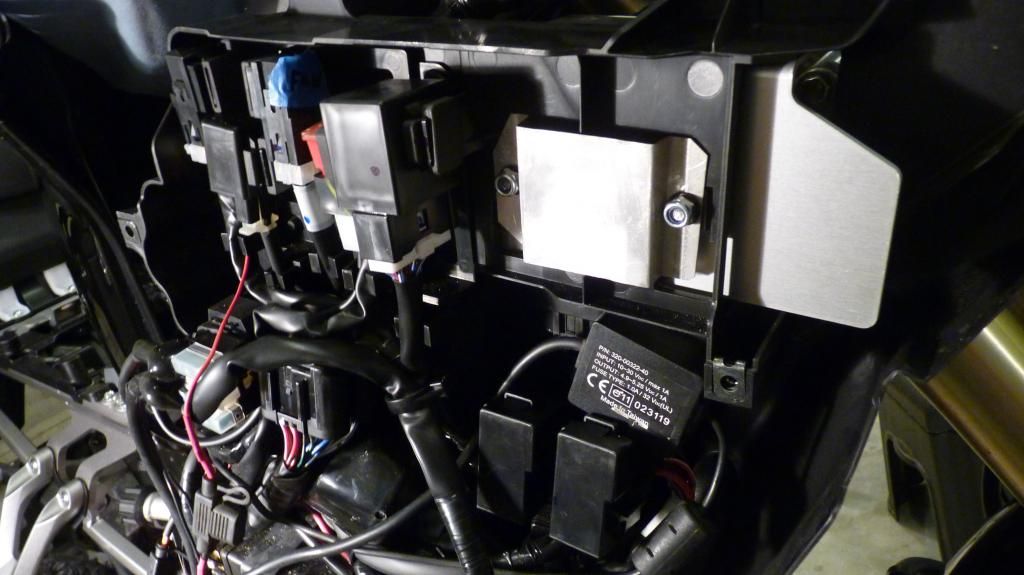
I attached the fuse block with double stick tape as shown here;
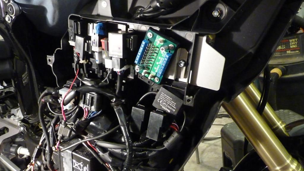
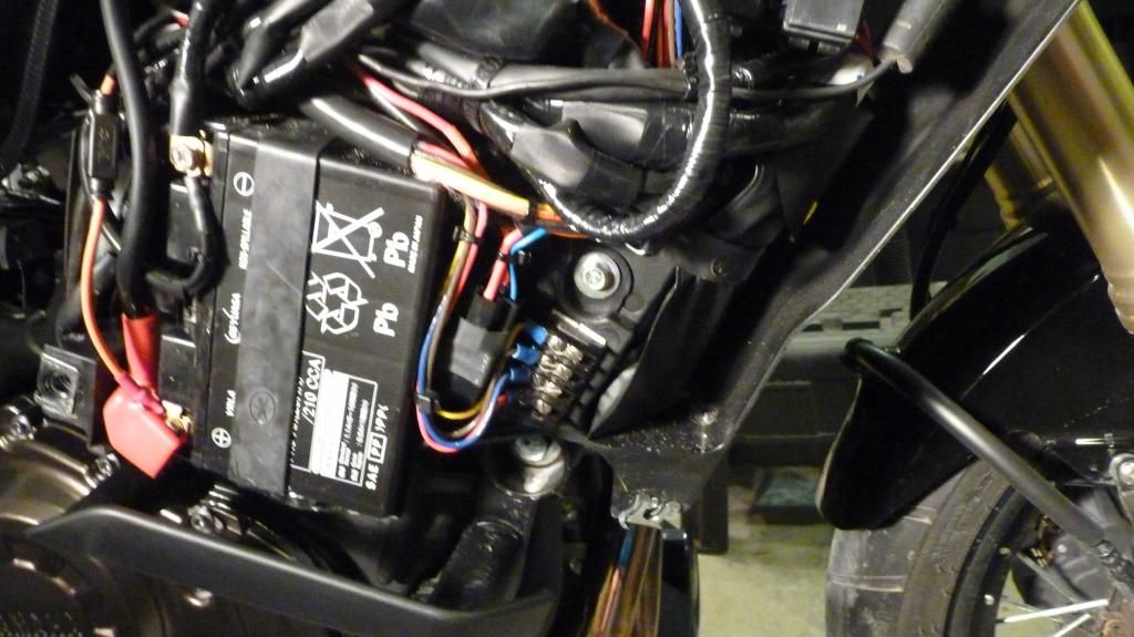
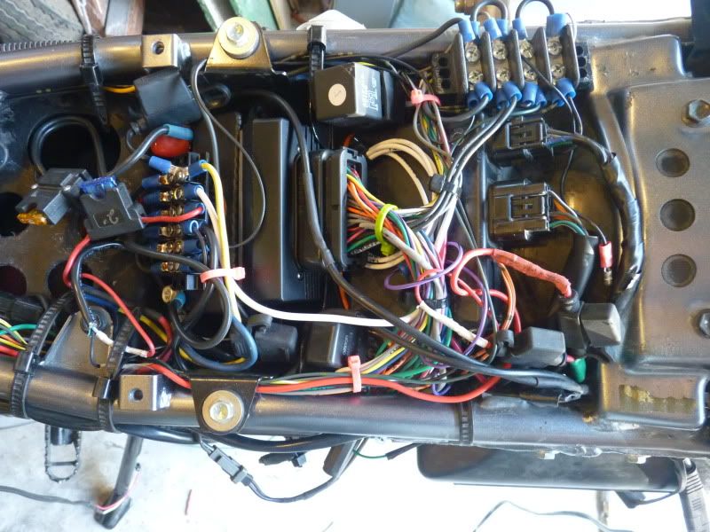
This picture is with some of the wiring installed:
In this photo you can see terminal strip for the switch outputs just to the right of the battery. It sits in the lower right hand corner of the bay.
The last thing I added was a set of ADVMonster model 60 LEDs and that used up the last panel switch. But I think I am about done with mods that require power for at least a little while. :
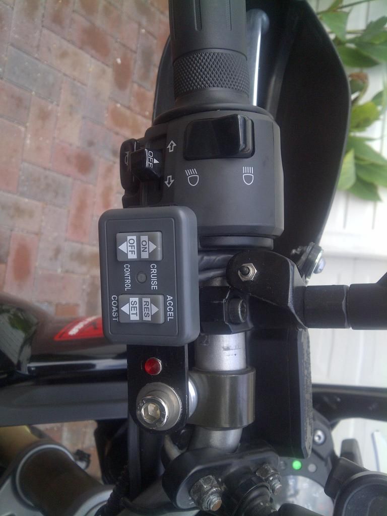
This is the left grip area showing the cruise control panel and the remote button to scroll the display (small button just above the cruise control panel).
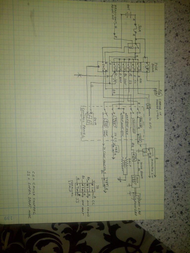
This is my circuit diagram for added wiring in the finished install. It does not include the wiring for the cruise control. I didn't want the diagram to get too complicated.
Thanks for reading this long winded post.
John ::001::
When I picked up my new S10 in August I had been thinking about all the mods and upgrades I wanted to make for some time.
I realized that many of them need electrical power and switches to control them. The list so far is: LED flood lights, cruise control, grip heaters, seat heaters, and a Super Sport mode (i.e. clutch switch short via relay). I also want to have a full time Digital Volt Meter (DVM) so I can monitor the health of the charging system at all times as I switch in different loads so as not to create an overload that goes unnoticed until the next time I try to start the beast up. With my luck, it will be when I am 1,000 from home. : So that is 5 switches and a meter. And that is in addition to the other non-stock handle bar area controls like a cruise control panel, remote button to scroll the display, seat heat thermostat, and GPS. Clearly I would have to add some kind of panel to hold some of this stuff or I would quickly run out of room. In addition I wanted to power all additions with a separate fuse block. This fuse block is fed by a relay that turns on only when the ECU determines that the engine is running. The ECU has a control line for that and it activates the head light relay. I just tied into the output of the head light relay.I had several goals here. One is to make sure I completely isolated my stuff from the bike’s electrical system so nothing I do can cause the magic smoke to leak out. I am an electrical engineer but still manage to screw up and leak smoke with alarming regularity. :-[ I also want to have each device on a separate fuse.
So here is what I ended up with. The switches are toggle and light up LED’s when turned on.
Here it is mounted on the bike:
And here is the wiring underneath. This explains better than words how it is constructed.
And this one is the finished panel under test prior to install.
The panel itself is made from 3/16” aluminum plate. It is held to the handle bars by two U bolts, 4 cap screws, and a couple of spacers underneath. I added a skirt of 3/4" plywood around the bottom outer edge just to give it some thickness and help protect the electrical parts. I just cut it out on the band saw and then cut out most of the middle to leave a thin strip. I found a 12 conductor cable at the local electrical surplus store. I used the cable to connect the panel to the fuse block down in the battery bay for switch power and to a terminal strip for switched power from the switch. Then all I had to do to add something was pick up the switched power at the terminal strip.
For the fuse block I used the very nice unit from Eastern Beaver. It came in a kit with the control relay. The first thing to figure out was where to mount it. A made a mounting plate from thin aluminum and bolted it to the back side of the rectifier as shown here:
I attached the fuse block with double stick tape as shown here;
This picture is with some of the wiring installed:
In this photo you can see terminal strip for the switch outputs just to the right of the battery. It sits in the lower right hand corner of the bay.
The last thing I added was a set of ADVMonster model 60 LEDs and that used up the last panel switch. But I think I am about done with mods that require power for at least a little while. :
This is the left grip area showing the cruise control panel and the remote button to scroll the display (small button just above the cruise control panel).
This is my circuit diagram for added wiring in the finished install. It does not include the wiring for the cruise control. I didn't want the diagram to get too complicated.
Thanks for reading this long winded post.
John ::001::