EdOnS10
2014 Super Tenere ES (Matte Grey)
happy 2015 All!
In case there are people out there trying to wire some new toys (like me") )- I thought it would be nice to play fill in the table... It seems there is an info gap out there for the 2014 ES models on the 4pin connectors. At least my googleFu was not up to the task... I would like to get some verified answers and then will edit the post to just read like a one-stop table for easy reference and easier searching... So if you can contribute, please let us know specific behavior of those plugs.
)- I thought it would be nice to play fill in the table... It seems there is an info gap out there for the 2014 ES models on the 4pin connectors. At least my googleFu was not up to the task... I would like to get some verified answers and then will edit the post to just read like a one-stop table for easy reference and easier searching... So if you can contribute, please let us know specific behavior of those plugs.
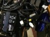
In particular - the 2014 ES seems to have a different wiring of the 4pin harness (next to the 3pin aux plug under the right pannel) than is described by other forum members with different models...
Unknown / unconfirmed :
4-pin Female Aux connector:
Black/White stripe = Ground
Red / Blue stripe = 12V Always ON (Fuse?)
Blue/ Black stripe = ?? Seems off, then around 3-4V with ignition? (but my DMM is jacked so I don't trust that)
Blue/ Red stripe = ?? Seems off, then around 3-4V with ignition? (but my DMM is jacked so I don't trust that)
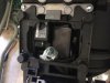
4-pin Male Connector - Under Seat:
Black = ??
Light Blue = ??
Light Green = ??
White / Red stripe = ??
Confirmed All Models
3-pin Female Aux connector (A.K.A. Aux Light Plug):
Black = Ground
Red / White stripe = 12V always on with 20A fuse
Brown = 12V on when ignition is on with 20A fuse
see = http://www.yamahasupertenere.com/index.php?topic=12961.msg206771#msg206771
Seems to be true for 2013- Models
4-pin Female Aux connector (A.K.A. Heated Grip Plug):
Blue/black stripe =12V when ignition is ON (Fuse?)
Black/green stripe =12V when headlights are on (Fuse?)
Black = Ground
Light Green/White Stripe = goes to ECU... not sure what that means behavior-wise...
2014+ all models
There are two true (two pin) heated grip connectors for the oem grips on the right side... See discussion and pic at http://www.yamahasupertenere.com/index.php?topic=14461.0
This is different than the 4pin aux plug, so we will have to stop calling it the grip connector.... The plot thickens ???
Additional Notes
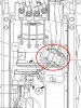
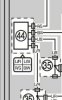
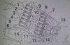
Fuses
See the picture below but:
2014+ 2013-
1. Headlight 20A Same
2. ABS solenoid 20A Same
3. Electronic Throttle valve 7.5A Same
4. Fuel Injection System 20A Same but 10A
5. Backup (for clock) 7.5A Same
6. Radiator Fan 20A Same
7. Ignition 20A Same
8. Signaling System 7.5A Same but 10A
9. ABS Control Unit 7.5A Same
10. Auxiliary DC Jack 3.0A Same
11. Parking Lighting 7.5A "Taillight" 7.5A
12. O/P (option) 20A Same
13. Suspension Fuse 15A (ES ONLY) N/A
14. Spare Fuses Same
elsewhere:
1. ABS Motor 30A (has spare next to it) - left of fuse boxes
2. Main Fuse 50A (has spare next to it 2014+) - upper cowling
3. Cruise Control 1.0A - upper cowling 2014+
4. BreakLight 1A - upper cowling 2014+
Found by JRE - some info on the breaklights (more info at http://www.yamahasupertenere.com/index.php?topic=1500.msg223366#msg223366)
If you have additional information on other connectors like the test harnesses under the seat - I would be interested to capture that here as well. But let's leave discussion about what to hook up where or how awesome Eastern Beaver modules are (they are honestly a great idea by the way) stuff to other threads.. That way the technical details don't get lost in another 10page thread...
Thanks in advance!!
::017::
In case there are people out there trying to wire some new toys (like me
)- I thought it would be nice to play fill in the table... It seems there is an info gap out there for the 2014 ES models on the 4pin connectors. At least my googleFu was not up to the task... I would like to get some verified answers and then will edit the post to just read like a one-stop table for easy reference and easier searching... So if you can contribute, please let us know specific behavior of those plugs.In particular - the 2014 ES seems to have a different wiring of the 4pin harness (next to the 3pin aux plug under the right pannel) than is described by other forum members with different models...
Unknown / unconfirmed :
4-pin Female Aux connector:
Black/White stripe = Ground
Red / Blue stripe = 12V Always ON (Fuse?)
Blue/ Black stripe = ?? Seems off, then around 3-4V with ignition? (but my DMM is jacked so I don't trust that)
Blue/ Red stripe = ?? Seems off, then around 3-4V with ignition? (but my DMM is jacked so I don't trust that)
4-pin Male Connector - Under Seat:
Black = ??
Light Blue = ??
Light Green = ??
White / Red stripe = ??
Confirmed All Models
3-pin Female Aux connector (A.K.A. Aux Light Plug):
Black = Ground
Red / White stripe = 12V always on with 20A fuse
Brown = 12V on when ignition is on with 20A fuse
see = http://www.yamahasupertenere.com/index.php?topic=12961.msg206771#msg206771
Seems to be true for 2013- Models
4-pin Female Aux connector (A.K.A. Heated Grip Plug):
Blue/black stripe =12V when ignition is ON (Fuse?)
Black/green stripe =12V when headlights are on (Fuse?)
Black = Ground
Light Green/White Stripe = goes to ECU... not sure what that means behavior-wise...
2014+ all models
There are two true (two pin) heated grip connectors for the oem grips on the right side... See discussion and pic at http://www.yamahasupertenere.com/index.php?topic=14461.0
This is different than the 4pin aux plug, so we will have to stop calling it the grip connector.... The plot thickens ???
Additional Notes
Fuses
See the picture below but:
2014+ 2013-
1. Headlight 20A Same
2. ABS solenoid 20A Same
3. Electronic Throttle valve 7.5A Same
4. Fuel Injection System 20A Same but 10A
5. Backup (for clock) 7.5A Same
6. Radiator Fan 20A Same
7. Ignition 20A Same
8. Signaling System 7.5A Same but 10A
9. ABS Control Unit 7.5A Same
10. Auxiliary DC Jack 3.0A Same
11. Parking Lighting 7.5A "Taillight" 7.5A
12. O/P (option) 20A Same
13. Suspension Fuse 15A (ES ONLY) N/A
14. Spare Fuses Same
elsewhere:
1. ABS Motor 30A (has spare next to it) - left of fuse boxes
2. Main Fuse 50A (has spare next to it 2014+) - upper cowling
3. Cruise Control 1.0A - upper cowling 2014+
4. BreakLight 1A - upper cowling 2014+
Found by JRE - some info on the breaklights (more info at http://www.yamahasupertenere.com/index.php?topic=1500.msg223366#msg223366)
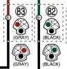
The brown wire is now dark gray with a blue stripe and the green and brown striped is now green and dark grey striped. To summarize:
Admore wires Bike Wires
-------------------------------------------
Blue & Red Blue
Purple Yellow
Green *Dark Gray and Green striped
Yellow *Dark Gray and Blue stripe
Black Black
*changes to the 2014+
If you have additional information on other connectors like the test harnesses under the seat - I would be interested to capture that here as well. But let's leave discussion about what to hook up where or how awesome Eastern Beaver modules are (they are honestly a great idea by the way) stuff to other threads.. That way the technical details don't get lost in another 10page thread...
Thanks in advance!!
::017::
Attachments
-
 56.5 KB Views: 392